|

|
 Home > Product
> Sterilization
disinfection device
|
|
|
|
 CHLORINE
DOSING
EQUIPMENT
|
|

|
| 
|
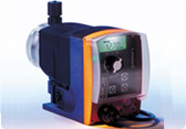
Chlorine
disinfection
device
is
the
equipment
injecting
chlorine
water
to
certain
amount
of
chlorine
residue
by
Diaphragm
Metering
Pump,
and
used
in
sterilizing
drinking
water,
cooling
circulation
water,
and
swimming
pool.
|
| 
|
| Cl²+H²O
|
↔
|
Cl².8H2O
|
↔
|
HCI+HOCI
|
↔
|
CI+OCI
|
|
Chlorine
water
|
Molecule
composition
|
Hypochlorite
|
Sterilizing
|
|
|
|
|
|
|
|
|
 ULTRA
VIOLET
STERILIZER ULTRA
VIOLET
STERILIZER
|
|

|
| 
|
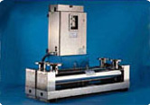
The
feature
of
ultraviolet
rays
sterilizer
is
that
the
water
gets
to
flow
outside
of
quartz
pipe
enclosing
lamps.
Quartz
pipe
takes
role
of
conveying
ultraviolet
rays
to
flowing
water,
and
get
rid
of
harmful
component
and
chemical
change
of
smell
and
taste.
There
are
two
kinds
of
wavelength
used
in
water
treatment,
which
are
254mm
and
185mm
in
UV.
|
|
|
|
|
|
|
MODEL
NO
|
MP-2-SL
|
CSL-4R
|
CSL-6R
|
CSL-8R
|
CSL-12R
|
CSL10R/60
|
CSL12R/60
|
|
Capacity CW(㎥/hr)
|
4.5
|
9.1
|
13.6
|
18.2
|
29.5
|
48.9
|
59.1
|
|
Capacity
DI(㎥/hr)
|
5.5
|
11.4
|
17.7
|
22.7
|
36.5
|
59.1
|
71.6
|
|
No
of UV
Lamp
|
2
|
4
|
6
|
8
|
12
|
10
|
12
|
|
Amps
@120
VAC
|
.80
|
1.9
|
3.0
|
3.9
|
4.6
|
5.8
|
6.5
|
|
Total
Power(Watts)
|
96
|
230
|
360
|
470
|
550
|
700
|
780
|
|
In/Out
Flange(A)
|
40
|
50
|
50
|
80
|
80
|
100
|
100
|
|
Housing
Material
|
SUS
304
|
|
Chamber
Material
|
SUS
316
|
|
Dimensions(LxWxH)
|
97x18x53
|
102x23x53
|
102x23x53
|
104x28x53
|
114x33x67
|
175x33x70
|
175x33x70
|
|
|
|
|
 OZONE GENERATION OZONE GENERATION
|
|

|
| 
|
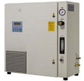
Ozone
generator
has
high
pressured
electrode
structure
that
special
metal
is
deposited
in
ceramic
tube,
and
generate
ozone
by
dielectric-barrier
discharge
plasma
injecting
oxygen
or
air
between
ceramic
tube
and
metal
ground
electrode.
By
microbe
gap
ozone
is
generated
and
high
pressure
electrode
in
inside
ceramic
tube
so
it
has
long
durability
in
structure.
It
can
used
without
additional
solving
facility
by
using
special
injector.
|
| 
|
Prevent
algae
in
cooling
tower
circulating
water
contamination
of
pathogenic
bacteria
|
|

|
Get
rid
of
polluted
waster
water’s
color
degree,
CCD
and
other
water
treatment’s
oxidation.
|
|
|
|
|
|
|
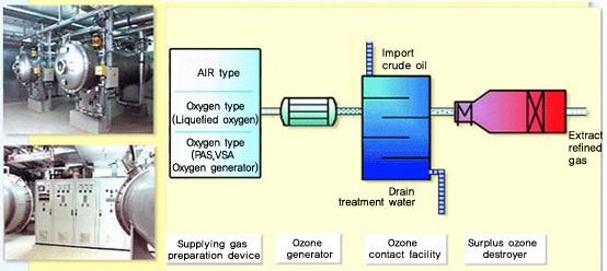
Schematic Diagram
of an Ozone Installation
|
|

|
|
|
|

|
|

|
NOMINAL
|
OPTIMUM
|
Out
Pressure
|
Oxygen
|
Cooling
water
|
Main
Power
|
|
Oxygen
6wt%
|
Oxygen
10wt%
|
Oxygen
|
for
6(wt%)
|
|
Units
|
g
O2/hr
|
Bar
|
N㎥/hr
|
㎥/hr
|
kw
|
|
Ib/Day
|
Psi
|
scfm
|
grm(us)
|
|
CFS-1
|
75
|
55
|
0.7
|
0.90
|
0.09
|
0.76
|
|
3.97
|
2.9
|
10.1
|
0.57
|
0.40
|
|
CFS-3
|
225
|
165
|
0.7
|
2.65
|
0.27
|
2.14
|
|
11.9
|
8.8
|
10.1
|
1.68
|
1.19
|
|
CFS-7
|
500
|
370
|
1.0
|
5.80
|
0.51
|
4.40
|
|
26.5
|
19.7
|
14.5
|
3.68
|
2.25
|
|
CFS-14
|
1,000
|
730
|
1.0
|
11.4
|
1.10
|
8.55
|
|
52.9
|
38.5
|
14.5
|
7.23
|
4.84
|
|
|
|